Looking at a photographic image from another point of view: Yours

Good writers can conjure a vivid image in our minds with just words. But journalists also have long relied on illustrations, photographs and videos to enrich a story.
Photographs and, by extension, videos have an important limitation. The story is told from one point of view – that of the photographer. The photographer structures our perception through his or her choice of focal point, depth of field and composition – with framing often eliminating as much as it includes. New technologies like light field photography, brought to the market by Lytro cameras, seek to change this by giving the user the control over what to focus on.
Another exciting technique is 3-D scanning that can capture real world objects with reasonable accuracy. Clyde Bentley, my colleague and a veteran of the news industry, uses the terms “captured reality” and “created reality” to distinguish 3-D content from 3-D video cameras from images that are purely computer generated. I am intrigued by the possibilities of 3-D scanning technology as it occupies the conceptual middle ground between captured and created realities. It also offers a great opportunity to test workflow strategies against issues pertaining to credibility. How do you strike a balance between efficient workflows with a short learning curve while ensuring credibility? What impact does a poorly captured and processed 3-D scan have on perceptions of source credibility?
The 3-D scanners — often referred to as reality capture tools or “ReCap” — have attracted great interest with software giants like Autodesk. While 3-D scanning technology has existed for some time, it was expensive — costing tens of thousands of dollars — and beyond the reach of most people. Advances in hardware technology and computer vision algorithms have resulted in more affordable 3-D scanners. The Structure Sensor by Occipital, the iSense from 3DSystems, Kinect, and ASUS Xtion Pro with appropriate software like Skanect all bring affordable 3-D scanning technology to journalists. The Structure Sensor has received a lot of attention since its highly successful Kickstarter funding.
Over the last few months I worked with my graduate assistants, James Hopfenblatt and Michael Lam, to explore the potential of these affordable 3-D scanners for use by journalists. We chose the Structure Sensor with Skanect software. We used the scanner in two ways: We used it with the itSeez3D app on the iPad for simple scans and with the Skanect software running on a mobile graphics workstation to capture larger, more complex objects. The latter approach allowed us to take advantage of the powerful graphics card of the laptop.
As I mentioned in my previous post, we are working on a story in 3-D about historic costume pieces. We want the audience to experience these costumes as if they were viewing the display in the recently renovated Gwynn Lounge inside Gwynn Hall on the University of Missouri campus. This meant recreating these historic pieces in 3-D. These historic costumes vary in the complexity of their shapes, textures and material finishes thereby providing an interesting testing environment. I am approaching this more in terms of experimenting with the workflow and tradeoffs of cost and quality without necessarily worrying about the time constraints that reporters in the field often have to deal with.
Bentley and his students also worked with the Columbia Missourian newspaper to test the Structure Sensor while covering the True/False Film Festival as part of our MU3D project. This gave our team a sense of real-world constraints faced by journalists in the field. You can see the results of their scans here and here.
Audiences rely on a number of heuristics to judge credibility of a story. As with any new technology, once the novelty wears off, I feel that the audience will be more critical in evaluating the content. Right now most of these scanners give a good approximation of the geometry and the texture, but appear to fall short when it comes to capturing detailed nuances. We were interested in seeing how much we can push the quality by enhancing the scan with 3-D modeling applications.
In our experiments, we ran into three main issues with these affordable scanners:
- The scanners were good at capturing the overall form, but fell short when scanning costumes with rich detail.
- Lack of use of elaborate lighting resulted in less-than-ideal texture rendering.
- Certain materials like satin, which have higher reflectivity, interfered with the scan and resulted in inaccurate geometry.
Just as personal computers replaced mainframes, we can expect 3-D scanners for the consumer market to improve in quality and price.
The key steps in our workflow are summarized below by James Hopfenblatt with images to illustrate the issues. In addition, here is a short video summarizing the workflow process and some of our considerations. George Varney, a capstone student at the Missouri School of Journalism who is working with us on this project, created the video.
Workflow for creating 3-D models of the historic costumes with the Structure Sensor
Developed by James Hopfenblatt
To scan the costumes, we used the Structure Sensor attached to an iPad and the Skanect software running on a Dell Precision Mobile Workstation with an Nvidia Quadro 1000 graphics card. We used Meshmixer and Autodesk Mudbox to refine the model and textures before bringing the finished model into the interactive Unity file. We will write about our process of creating the interactive pieces in Unity in another detailed blog. The key steps in the workflow are summarized below.
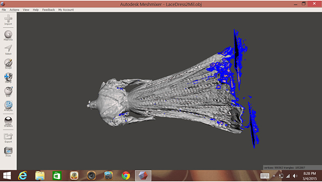
Import Scan data from 3-D Scanner into MeshMixer (or equivalent geometry-fixing software).
MeshMixer will pinpoint locations in the original scan that contain errors and perform an automated repair, or allow user to fix errors manually. (Other software that will perform these operations include 3-D coat and Zbrush.)
At this stage, the scan data can be reduced and focused on a specific area while ignoring a portion of the scan.

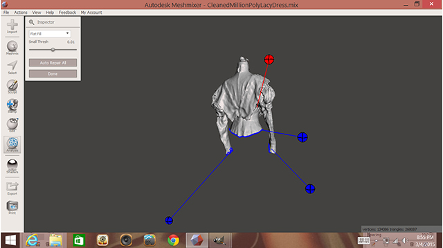
After selecting a portion of the scan and performing automated fixes, additional areas can be fixed manually if needed.
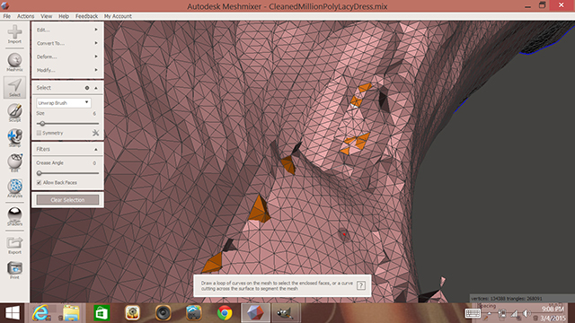
The inside of the model is visually analyzed and different locations that are too dense in vertices or polygons are selected, simplified and flattened (see next example). Other areas that can be fixed are back-faces, which won’t show on the final model and add unnecessary complexity.
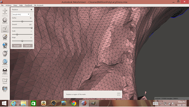
Selected peaks on the interior of the model are flattened with the “edit -> erase and fill” option or by pressing the F key.
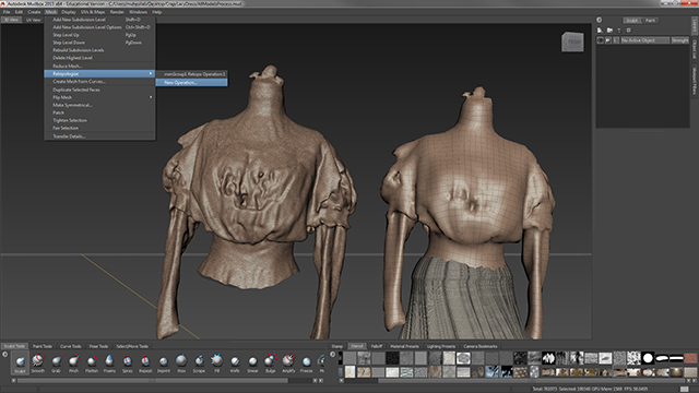
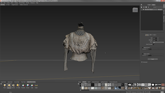
The reduced/fixed portion of the model is then brought into Autodesk Mudbox where the geometry is turned from a triangulated mesh into a quad-based mesh — a format more suitable for texturing and animation. This option is found under Mesh -> Retopologize -> New Operation. Mudbox will also create five subdivision levels (mesh complexity + detail levels). This allows for the option of extracting a simplified version of the model to be used.
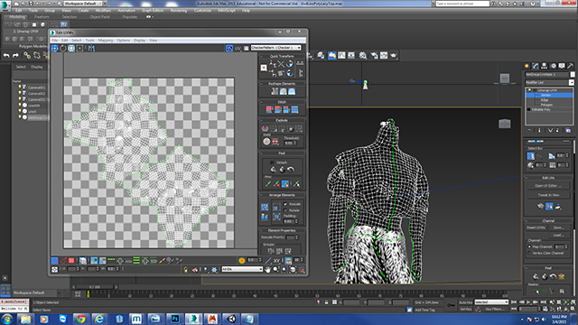
The simplified version of the model is then UV-mapped in 3-D Studio Max.
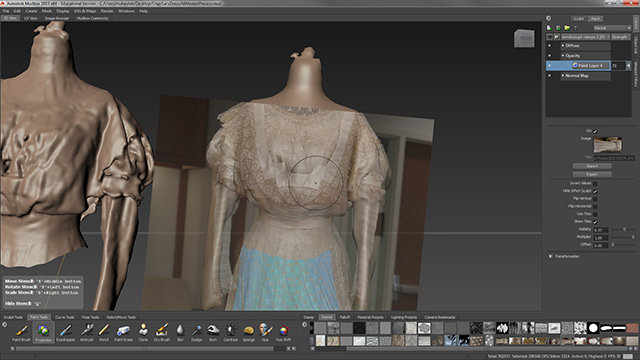
The simplified model’s UV map is brought back to Mudbox and photographs can be directly painted on top of the simplified mesh with the Projection tool. Photographs used must be added to the Stencil box at the bottom.
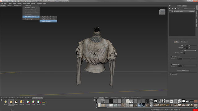
At this stage the complex model’s topological information can be mapped onto the simplified layer (in the form of a Normal Map) by going to UVs & Maps -> Extract Texture Maps -> New Operation -> Normal Map.
Once you’ve finished painting and creating Normal Map on model, it can be exported and used in various Game Engines. Because of the simplified geometry, animations and simulations are also possible on the scanned mesh.
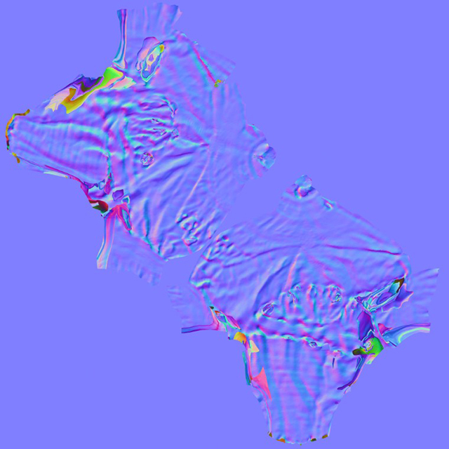
Normal maps are extracted from the complex model onto the UV map of the simplified model.
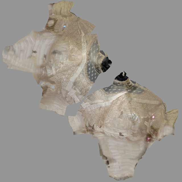
The painted photographs are also mapped onto the model through UV-mapping.
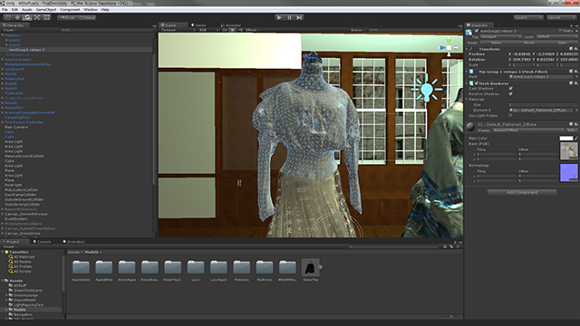
The finalized model being used inside of Unity — a game engine used to create interactive presentations and games.
Comments